
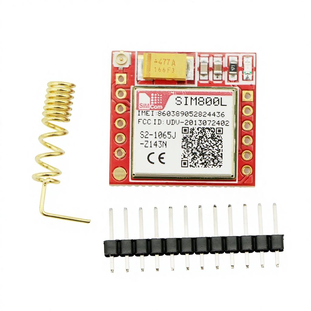
Description
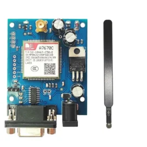
This is Small SIM800L GPRS GSM Module Micro SIM Card Core Board Quad-band TTL Serial Port with the antenna, in this module two antennas have been included. SIM800L GSM/GPRS module is a miniature GSM modem, which can be integrated into a great number of IoT projects. You can use this module to accomplish almost anything a normal cell phone can; SMS text messages, make or receive phone calls, connecting to the internet through GPRS, TCP/IP, and more! To top it off, the module supports quad-band GSM/GPRS network, meaning it works pretty much anywhere in the world.There’s a SIM socket on the back! Any activated, 2G micro SIM card would work perfectly. The correct direction for inserting the SIM card is normally engraved on the surface of the SIM socket.
This module measures only 1-inch ² but packs a surprising amount of features into its little frame. Some of them are listed below:
Supports Quad-band: GSM850, EGSM900, DCS1800 and PCS1900
Connect onto any global GSM network with any 2G SIM
Make and receive voice calls using an external 8Ω speaker & electret microphone
Send and receive SMS messages
Send and receive GPRS data (TCP/IP, HTTP, etc.)
Scan and receive FM radio broadcasts
Transmit Power:
Class 4 (2W) for GSM850
Class 1 (1W) for DCS1800
Serial-based AT Command Set
FL connectors for cell antennae
Accepts Micro SIM Card
Netlight LED Blinking Finding Network Connection
SIM800L GSM Module Pinout
The SIM800L module has a total of 12 pins that interface it to the outside world. The connections are as follows:
NET is a pin where you can solder the Helical Antenna provided along with the module.
VCC supplies power for the module. This can be anywhere from 3.4V to 4.4 volts. Remember connecting it to a 5V pin will likely destroy your module! It doesn’t even run on 3.3 V! An external power source like a Li-Po battery or DC-DC buck converters rated 3.7V 2A would work.
RST (Reset) is a hard reset pin. If you absolutely got the module in a bad space, pull this pin low for 100ms to perform a hard reset.
RxD (Receiver) pin is used for serial communication.
TxD (Transmitter) pin is used for serial communication.
GND is the Ground Pin and needs to be connected to the GND pin on the Arduino.
RING pin acts as a Ring Indicator. It is basically the ‘interrupt’ out pin from the module. It is by default high and will pulse low for 120ms when a call is received. It can also be configured to pulse when an SMS is received.
DTR pin activates/deactivates sleep mode. Pulling it HIGH will put the module in sleep mode, disabling serial communication. Pulling it LOW will wake the module up.
MIC± is a differential microphone input. The two microphone pins can be connected directly to these pins.
SPK± is a differential speaker interface. The two pins of a speaker can be tied directly to these two pins.
Reviews
There are no reviews yet.